Adding parameters to Hydrostatics
Create a new class along side Dimensions and call it General.
- Create the following parameters (all are values) within the Knowledge Browser:
Parameter name | Dimension | Determined by | Reference | In Class |
| [-] (none!) | VR: User only | Block coefficient | Dimensions |
| [t] | USR: User or System/equation | Displacement of vessel at design draft | Dimensions |
| [t/m^3] | VR: User only | Density of water | General |
| [m] | VR: User only | Design draft of ship | Dimensions |
| [m^3] | USR: User or System/equation | Hull volume at design draft | Dimensions |
- Next drag and drop the parameters:
Lpp,Boa,Cb,Displacement,Rho,T_designandVolumefrom the Knowledge Browser into the entityHydrostatics.
Incidentally, the parameters Displacement and Volume still have their red crosses because they are not completely defined. You will add relations for them in a minute.
Creating a drop down box
- To show 3 decimal places for parameter
Rho, change the number of decimals places into 3 in the Properties window of parameterRho.
Because their will only be two possible values for parameter Rho (1.025 or 1.000 [t/m3]), it is useful to create a dropdown box. This can be done by providing a special reference.
- Select the Parameter tab of the Properties window for
Rho. - In the Reference field type the following:
Density of water. Select water type;1.025<EQ>Saltwater1.000<EQ>Freshwater
Creating entity relations
In the Hydrostatics entity, calculations need to be performed based upon information from Main Dimensions and some relation. In order to achieve this, you have to create so called entity-relations. The first entity-relation to create will be for parameter Boa in entity Hydrostatics: the value of Boa in entity Hydrostatics should be equal to the value of Boa in entity Main Dimensions.
- Right-click on the parameter
Boain entityHydrostaticsin the Workbase and select Taxonomy > Create Relation or press Ctrl+T.
The Expression Editor opens:
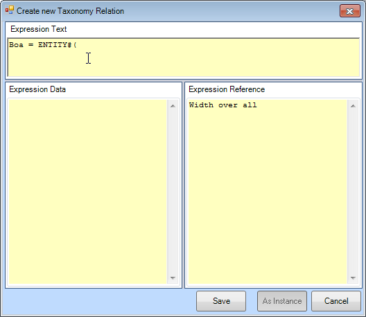
Providing a relation in the (upper part of) the Expression Editor will add a relation to the system, which is only valid in entity Hydrostatics.
Because the most common purpose of an entity-relation is to refer to other entities, the Expression Editor for entity relations is started up with the ENTITY#() function already there.
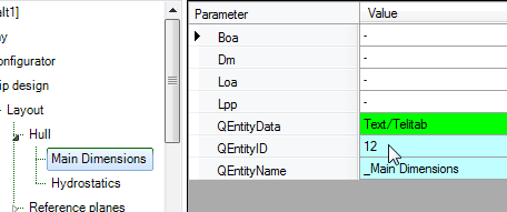
By providing the unique and correct QEntityId within the ENTITY#() function, you can refer to information in other entities. You will want to refer to information in Main Dimensions. So, you need the unique QEntityId of this entity.
There are two ways to get this ID:
- Look-up the ID by browsing to the entity in the taxonomy and read the QEntityId: The QEntityId of Entity “Main Dimensions” is 12. Figure 53 shows that QEntityId = 12 for Entity “Main Dimensions”.
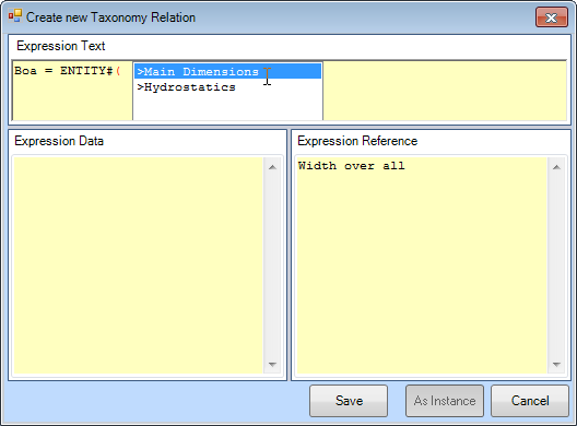
- Inside the Expression Editor, press Right-Arrow to initiate a “walk through” menu to navigate through all entity levels in your taxonomy (showing QEntityNames). Repeatedly scroll and press Right-Arrow until you have reached the entity you want, press Enter, and its ID will be filled in in the expression.
The value of QEntityID of Main Dimensions as presented in this tutorial could differ from yours, because it depends on the sequence in which you have created entities.
After selecting/entering the correct ID, placing the closing bracket and placing the dot, Quaestor will show all available parameters in the selected entity. You can scroll to the correct parameter and press Enter to select the parameter.
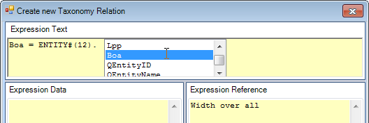
- Enter the following relation and click Save.
Boa = ENTITY#(12).Boa
This means Boa is equal to (will copy the value of) the Boa of the entity with QEntityID = 12.
Hereafter, the cell colour of Boa in Hydrostatics has turned to yellow.
To reset the parameter back to an input value, Right-Click on it the Workbase and select Taxonomy > Value = Input or press Ctrl+T again.
To edit an entity relation, Right-Click on the pertaining parameter in the Workbase and select Taxonomy > Edit Relation or press Ctrl+M.
An entity relation is something special. If you have experience with creating Quaestor knowledge bases (see the Tutorials on Quaestor basics), you will know that normally, a relation will be visible in the Knowledge Browser. Entity relations however, will only show themselves by the yellow colour of their parameters and the relation can only be shown by pressing Ctrl+M.
- Create an entity relation for
Lppin entityHydrostaticsin the same way. This parameter must be equal to the value ofLppin EntityMain Dimensions:
Lpp = ENTITY#(12).Lpp
Finally, relations must be provided to calculate Displacement and Volume in entity Hydrostatics. The following calculations should be made:
Displacement = Cb * Lpp * Boa * T_design * Rho
Volume = Cb * Lpp * Boa * T_design
These relations can be created in two ways:
- Add the relations to the taxonomy like above by Ctrl+T and then delete ENTITY#() and enter the expression.
- Add the relations to the Knowledge Browser and include these for the parameters in an entity.
The second method is very convenient when you know that a particular relation might be used in several entities. By adding the relation to the Knowledge Browser, you can connect is several times to different parameters in different Entities, saving a lot of time. TODO
- Create
Volumeusing the first method.
The second method will be used for parameter Displacement, which is explained below.
Connecting existing relations to entities
Start with creating one or more relations in the Knowledge Browser.
Select parameter “Displacement” in the right window of the Knowledge Browser, then right click, and select option “New relation...”(or CTRL + N). The Expression Editor opens and you can type the expression “Displacement = Cb*Lpp*Boa*T_design*Rho”. In this way the relation is added to the knowledge base (and not only to the Entity in the Taxonomy). However, realise that it is not yet connected to the parameter in the Entity of your Taxonomy.
To connect the relation, in the Workbase select the parameter “Displacement” in Entity ‘Hydrostatics”. Then, select the right mouse button menu Taxonomy>Choose/create relation or press Ctrl+T. A window will open showing the available relations for the selected parameter in the Knowledge Browser.
You can browse through the available relations and select the relation you want to use to compute the parameter, see Figure 67. In this case select the relation you have just created. The same method can be used to include any available relation for any selected parameter.

Figure 67: Include relation from Knowledge Browser in Entity
Furthermore, please note that it is still possible to create a new taxonomy relation by selecting the first option in presented window.
2.3.3.4 Provide the possibility to enable users to modify calculated values
In the first part of the tutorial, with parameter “Volume”, it was shown that it is possible to enable the user to modify calculated values after they are determined by the system. We can enable this functionality by adding a @MODIFY attribute to the data slot of the parameter.
First select parameter “Volume” in the right field of the Knowledge Browser and switch the radio button of the Frame Viewer to the data mode. In here you have to type @MODIFY, see Figure 68.

Figure 68: Provide parameter "Volume" with a @MODIFY attribute
2.3.2.4 Affect presentation sequence of parameters
It can be desirable to affect the sequence of parameters presented in the Workbase list during a dialogue. Normally Quaestor presents parameters in an alphabetical sequence. An @ORDER attribute in the Data Slot of a parameter defines the relative position of a parameter in the Workbase list. Define this position by: @ORDER:RelativePosition, in which RelativePosition is an integer. The higher the value of RelativePosition, the later the value is placed in the list. The @ORDER values of parameters to be presented need not to be subsequent values. Parameters are sorted on RelativePosition. Values with no @ORDER attribute are placed behind parameters with the @ORDER attribute.
We will explain this option only by placing parameter “Loa” at the top of the list. It is up to you to order the other parameters. First select parameter “Loa” in the right field of the Knowledge Browser and switch the radio button of the Frame Viewer to the data mode. In here you have to type “@ORDER:1”, see Figure 55 and Figure 56.
Please note figures in this tutorial can present the sequence of parameters different in comparison with your knowledge base. In that case probably parameters are ordered with @ORDER attributes. It is up to you to do the same.

Figure 55: Order parameters with @ORDER attribute in Data Slot of parameter

Figure 56: Loa on top of the list because of @ORDER: 1 in Data Slot of parameter
2.3.3.5 Define minimum and maximum values for parameters
Another interesting feature to assist the user is providing feedback about minimum and maximum input values. Moreover, you could make these boundaries into hard ranges in order to protect the user against providing value that might cause faulty results.
As an example we want to define a minimum and a maximum for the parameter “Cb”. This value must be between 0 – 1.0 [-].The system should issue a warning if the computed or input value is not within the indicated boundaries. This is done by means of the attributes @MAXVAL and @MINVAL.
When you want to make sure that this range cannot be superseded you also have to add the attribute @HARDRANGE.
Thus, the following attributes have to be added to the parameter “Cb” (how to add attributes to a parameter is described in 2.3.3.4.):
@MAXVAL:1.0
@MINVAL:0
@HARDRANGE
2.3.3.6 Show computed values during the dialogue
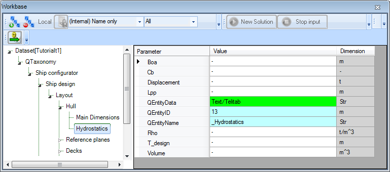
To show computed values during a dialogue you have to include the standard Quaestor parameter “QEntityData” (with the drag and drop functionality) from the Knowledge Browser in Entity “Hydrostatics”. You will find the parameter by either typing its name in the search box of the Knowledge Browser (field 1 of Figure 32). Or go to the top node of the tree in the Knowledge Browser (with the name of your knowledge base) and search in the list on the right side.
After dragging and dropping the parameter to the Entity, write “@SHOW” within the value of this parameter. Now, computed values in this Entity will always be shown during a dialogue. Figure 69 presents the result for Entity “Hydrostatics”.

Figure 69: Entity "Hydrostatics" in taxonomy
2.3.4 Strategy for adding relations in taxonomy type of knowledge bases
Before we continue with the next Entity, we want to give more insight in the creation of relations in taxonomy type of knowledge bases. In the previous paragraph you have noticed that we created Entity-relations, paragraph 2.3.3.2 above and “normal” relations, paragraph 2.3.3.3 above. But why do we have two different methods?
You have three ways of adding and using relations:
- Adding an Entity relation to the Entity in a Taxonomy;
- Add a relation to the Knowledge Browser and connect it to a parameter in an Entity;
- Create a relation in the Knowledge Browser and let the modeler determine which relations to use to determine a parameter in an Entity. This is only facilitated when all parameters in the Entity will be determined by the modeler.
Three important remarks can be made about the use of the different relation types:
- The general approach is to create Entity relations when you are developing a Taxonomy type of knowledge base.
Only used normal relations when you want to use the modeling/reasoning functionality of Quaestor. You might want to use the modeler when you want to execute complex models which make use of reasoning an advantage over a normal traditional fully hardcoded model (which a Taxonomy is to some extent). This is the case when you want the structure (network of relations) of a model to be dependent on the choices made and input provided by the user. - The main reason to use normal relations and connecting them to parameters in an Entity is when you know that the relation will be used on multiple positions in the Taxonomy. In that case you rather create one relation and connect it to the parameters in the relevant Entities.
- Use the ENTITY# function only in combination with Entity relations. You can use this function in normal relations but this is not advisable. The reason for use only in Entity relations is that, in case of an Entity relations, the EntityID in the ENTITY# function will be renumbered when modifications are made to the Taxonomy that cause Entities to be renumbered. This renumbering in the relation will not take place for normal relations.
2.3.5 Entity “Reference planes”
First create the following Entities as a child of Entity “Reference planes”.
Transverse planes | child of “Reference planes” | Entity type: singular obligatory |
Horizontal planes | child of “Reference planes” | Entity type: singular obligatory |

2.3.6 Entity “Transverse planes”
We want to create the possibility for the user to define a table containing a number of transverse reference planes. In section 4.6 of the first part of the tutorial, the goal for Entity “Transverse planes” is described in detail.
For each plane the user has to define a position and a name.
First create the following parameters in the Knowledge Browser. Please note that “Name$” is a string parameter and not a value.
Parameter name | Dimension | Reference |
Nr | [#] | Number of instances |
Name$ | [$] | Name of object |
CaseID | [-] | Case index |
Frame_Nr | [-] | Frame number |
Frame_spacing | [mm] | Frame spacing |
X | [m] | X position, in longitudinal direction |
The parameters “Nr”, “Name$”, “Frame_Nr” and “Frame_spacing” will be determined by “VR: User only” (indicate “VR” in Slots & Properties of parameter).
Now drag and drop the parameters in “Transverse planes“: “Nr”, “Name$”, “CaseID”, “X”, “Frame_Nr” and “Frame_spacing”.
Figure 70 shows all parameters in Entity “Transverse planes”.

Figure 70: Parameters in Entity Transverse planes
2.3.6.1 Let a parameter change the number of cases in an Entity
We will use parameter “Nr” to indicate the number of cases (columns) in an Entity.
Provide parameter “Nr” with the special attribute @NRINST in the Data Slot of the parameter. The @NRINST attribute tells Quaestor that the value given/calculated for this parameter indicates the number of instances/cases in an object (in this case an Entity).
Furthermore it is useful to provide “Nr” also with the attribute @INTEGER, see Figure 71. The @INTEGER attribute limits input or computed values of the parameter to integer values. If other than integer values are either computed or provided, the system issues a warning and prompts for other input or for other input of the related input.

Figure 71: Nr parameter, indicates number of instances within Entity
Moreover, for integer value you could also change the number of decimal places to 0.
2.3.6.2 Force parameters to show in the table (make parameters multi case)
Normally, any single (constant) value is placed in the list view, see Figure 4.
The @MULTVAL attribute forces single value parameter to present itself in the table of an Object/Entity. The @MULTVAL attribute is used in parameters if you wish to obtain a table which includes all values of these parameters whether they are single (constant) values or not. Figure 17 in chapter 4.6 of the first part shows an example.
We want the following parameters to be shown in the table: “Name$”, “CaseID”, “Frame_Nr” and “X”. So you have to provide @MULTVAL attribute in the Data Slot of these four parameters. By doing this you can see the location of these parameters are moved from list view to table view (you might have to force Quaestor to review the Workbase by switch between Entities). Please notice the differences between Figure 70 and Figure 72.

Figure 72: Parameters with @MULTVAL attribute in Entity Transverse planes
2.3.6.3 Relation for X position of transverse reference plane
Select parameter “X” in Entity “Transverse planes” in the Workbase. Select the right mouse button menu Taxonomy>Choose/create relation or press Ctrl+T. Create the following relation:
- X = Frame_nr * (Frame_spacing/1000)
For each case, representing a transverse reference plane, this relation will be calculated. Parameter “Frame_spacing” does not contain a @MULTVAL attribute, thus the value provided for “Frame_spacing” will be constant for each case.
2.3.6.4 Provide default values
It is possible to provide a proposed default value for “Frame_spacing” in the solution that can be overruled by the user by simply providing this value for the parameter in the Entity. For example, type 700 in the value cell of Frame_spacing”.
2.3.6.5 Use of ORCA() function to calculate numbers for each case: CaseID
Select parameter “CaseID” in Entity “Transverse planes” in the Workbase. Select the right mouse button menu Taxonomy>Choose/create relation or press Ctrl+T. Create the following relation:
- CaseID = ORCA(1)
The function ORCA(1) returns the current case number which is now being executed. Later on we will use this calculated value to refer to one of these transverse reference planes.
Please note that you also could have made a relation in the Knowledge Browser and connect it to the parameter (the second method for Entity relations, see 2.3.3.2) because you will use the same relation for the horizontal reference planes.
2.3.6.6 Include standard Quaestor parameters: QEntityData, QEntityDoc and QEntityRef to illustrate and describe the Entity
Include (with the drag and drop functionality) from the Knowledge Browser the standard Quaestor parameters “QEntityData”,“QEntityDoc” and “QEntityRef” in Entity “Transverse planes”. These parameters will not be visible for users of your knowledge base.
- To show the computed values for this Entity “Transverse planes” during a dialogue write “@SHOW’ behind “QEntityData”.
- You can add a picture in “QEntityDoc”, which explains definitions of reference planes and the coordinate system of the vessel to the user in the Explanation window.
Select QEntityDoc in Entity “Transverse planes” and select the right mouse button menu Taxonomy>Include Binary Data orCtrl+B, see Figure 73. Browse to the file you want to include, we propose the provided picture “reference_planes.bmp”.

Figure 73: Include Binary data in standard Quaestor parameter QEntityDoc
- Comparable to assigning reference to a parameter, you can assign a reference to an Entity. Behind the included “QEntityRef” you can assign an unlimited Entity reference text, which will be shown in the html Explanation window. For example; “Define number of transverse reference planes”
2.3.6.7 Define a Entity specific presentation name for a parameter
You can use a @WBNAME parameter attribute to define a presentation name to the user. For example, you want to define a presentation name “Number of transverse reference planes” for “Nr”.
Because you want this presentation name to be unique within Entity “Transverse planes” you cannot simply add the attribute to the data slot of the parameter.
First you have to select parameter “Nr” in Entity “Transverse planes” and select the right mouse button menu Taxonomy>Instantiate“Nr” (or Ctrl+E). Now for the parameter the textfield is shown yellow in the frame viewer for both the reference and data slot. This means that you are now able to provide a reference text and attributes for the parameter which differs from the global reference text and attributes for this parameter.
You can restore the global settings by doing the same action, but now the option Set global ”Nr” is available instead of Instantiate “Nr”.
After instantiating parameter “Nr” in Entity “Transverse planes” you can provide the following attribute in the Data Slot of the frame viewer; @WBNAME:Number of transverse reference planes. Furthermore you can change locally the reference text for “Nr” which is more applicable to Entity “Transverse planes”. For example, “Number of transverse reference planes” instead of “Number of instances”. Again note the text is written cursive, because you have instantiated the parameter “Nr”.
The same you can perform for parameter “Name$”. First instantiate parameter “Name$” in Entity “Transverse planes” and provide the following attribute in the Data Slot of the frame viewer: @WBNAME: Name of reference plane. Again you can change locally the reference text for “Name$” which is more applicable to Entity “Transverse planes”. For example, “Name of transverse reference plane” instead of “Name of object”.
Please note, you are able to define a presentation sequence of parameters (within a specific Entity) by providing @ORDER attributes forinstantiated parameters. See 2.3.2.4, for the explanation of @ORDER attribute.
Finally Entity “Transverse planes” should more or less look like Figure 74.

Figure 74: Entity "Transverse planes"
2.3.7 Entity “Horizontal planes”
The explanation for this paragraph will be extensive than the previous, because most of the actions that have to be performed are equal to the actions described above.
The main goal is that we want to create the possibility for the user to define a table with a number of horizontal reference planes. For each plane the user has to define a position and a name.
- First create the following parameter in the Knowledge Browser.
Parameter name | Dimension | Reference |
Z | [m] | Z position, in vertical direction |
- Provide parameter “Z” also with an attribute @MULTVAL in the Data Slot of the parameter.
- Next include the following parameters in Entity “Horizontal planes“: “Nr”, “Name$”, “CaseID”, “Z”, “QEntityData”, “QEntityDoc”and “QEntityRef”.
- Parameters “Nr”, “Name$” and “Z” will be requested to the user (so all are VR parameters). Instantiate the parameters “Nr” and “Name$” in Entity “Horizontal planes” and provide for both parameters a @WBNAME attribute to define a presentation name for the user.
- Create the following relation CaseID = ORCA(1)
- To show computed values during a dialogue write “@SHOW” behind “QEntityData”.
- Add picture “reference_planes.bmp” as Binary to “QEntityDoc”.
- Assign the following text for “QEntityRef”; “Define number of horizontal reference planes”
Now your developed Entity “Horizontal planes” should more or less look like Figure 75.

Figure 75: Entity "Horizontal planes"
2.3.8 Entity “Decks”
Entity “Decks” will be developed as a container which contains combined data of all defined singular decks below. As child of Entity “Decks” we include the multiple (select one of more) Entity “Deck”.
| Deck | child of “Decks” | Entity type: Multiple (select one of more) |

As depicted in Figure 21 below Entity “Decks” can contain one or more “Deck” Entities, each containing the same parameters and relations; however the user can provide different input values for every Deck.
During the dialogue the user will be asked the number of Deck Entities he wants to include. If you include the “Nr” parameter in the “container” Entity “Decks” this will be the parameter which determines the number of “Deck” Entities that will be placed, because “Nr” contains an @NRINST attribute in the Data Slot, as explained in 2.3.6.1.
- Create the following parameters in the Knowledge Browser.
Parameter name | Dimension | Reference |
Total_deck_area | [m^2] | Total deck area |
Deck_data# | [Telitab] | Table of deck data |
Total_accommodation_area | [m^2] | Total accommodation deck area |
Total_accommodation_area# | [Telitab] | Table of all accommodation deck data |
Please note “#” behind a parameter name automatically indicates this will be a Telitab in Quaestor, which mean this parameter can contain Text, a List or a Table. We now will use it to create a Table. For more detailed information about a TeLiTab see TeLiTab.
- Next include the following parameters in Entity “Decks“: “Nr”, “Total_deck_area”, “Deck_data#”, “Total_accommodation_area”, “Total_accommodation_area#”, “QEntityRef” and “QEntityData”.
We will include relations for these parameters at a later stage (in paragraph 2.3.10), because these will be clearer to you when you first have developed Entity “Deck”.
2.3.9 Entity “Deck”
- Create the following parameters in the Knowledge Browser.
Parameter name | Dimension | Reference |
B | [m] | Width |
Area | [m^2] | Area |
Deck_function$ | [$] | Define function of deck |
L | [m] | Length |
Weight_area_factor | [t/m^2] | Weight factor per area |
X_aft | [m] | Aft deck position in X (longitudinal) direction |
X_front | [m] | Front deck position in X (longitudinal) direction |
X_aft_plane_ID | [ID] | Define aft (longitudinal) position of deck by selecting a transverse reference plane |
X_front_plane_ID | [ID] | Define front (longitudinal) position of deck by selecting a transverse reference plane |
Z_plane_ID | [ID] | Define Z (vertical) position of deck by selecting a horizontal reference plane |
- Next include the following parameters in Entity “Deck“: “Name$”, “Area”, “B”, “Deck_function$”, “L”, “Weight_area_factor”, “X_aft”, “X_aft_plane_ID”, “X_front”, “X_front_plane_ID”, “Z”, “Z_plane_ID and “QEntityData”.
Provide the following relations (the explanation of the relations will follow):
- B = ENTITY#(xx).Boa (for xx fill in the value of QEntityId of Entity “MainDimensions”
- Area = L*B
- L = X_front - X_aft
- To show computed values during a dialogue write “@SHOW” behind “QEntityData”.
Please note all parameters in Entity “Deck” should be in the list View and not in the table view, because all values are constant single values. So, parameters “Z" and “Name$” “in Entity “Deck” are automatically placed in the table view because you have provided a @MULTVAL attribute to these parameters earlier. You can instantiate the parameters in Entity “Deck” and remove the @MULTVAL attribute locally.
A second option is to provide @NOMULTVAL attribute in parameter “QEntityData” of Entity “Deck”. Now all @MULTVAL attributes within this Entity will be ignored.
The user (ship designer) has to indicate the starting position and end position of a deck in longitudinal direction of the ship, with the parameters “X_aft” and “X_front”. This determines the length “L” of the ship. Next we assume the width “B” of a deck is equal to the width over all “Boa” of Entity “MainDimensions”. To assume rectangular decks the area is calculated by L*B.
You might wonder why we have added the “Weight_factor_area” parameter. Although we will come to this in section 2.4.1.2 of this part, the main reason is that this parameter is a property of the Deck and as such should part of the “Deck” Entity. However, hereafter we will discover that we do not want to give the input for this value in this Entity, but as part of the “Mass calculation” Entity. In order not to show the parameter in this Entity do the following:
- Instantiate the parameter;
- Add the @HIDE attribute to hide is.
How to connect the start and end position to the reference planes will be discussed next.
2.3.9.1 Create selection list of reference planes with @SELECTENTITY attribute to position deck
We want to create a selection list from available data to position a deck according to specified reference planes in the reference Entities.
The way to do this will be explained by determining the aft position of a deck.
Include the following attributes in the Data Slot of parameter “X_aft_plane_ID”, see Figure 76:
- @SELECTENTITY; the value or string Entity attribute @SELECTENTITY:QEntityID is used to create a selection list from data available in other Entities. You have to replace QEntityID with the value of QEntityID you want to refer to, in this case Entity ““Transverse planes”.
- @SELECTENTITYKEY; the value or string parameter attribute @SELECTENTITYKEY:PAR is used to define the key parameter for the selection in a table of the Entity selection list (created by @SELECTENTITY). You have to replace PAR with the parameter you want to select. In this case we want to select the value of parameter “CaseID”.
- @SELECTENTITYKEYTEXTPAR; the value or string parameter attribute @SELECTENTITYKEYTEXTPAR:PAR is used to define the parameter for selection in the Entity in the Entity selection list, a pointer to a sub Entity. In this case we want to select the value of parameter “Name$”
- @EQEXPLAIN; the value or string parameter attribute @EQEXPLAIN is used to show the description instead of the values (for instance in a combo box).

Figure 76: Create selection list of transverse reference planes with @SELECTENTITY attribute
Please note that the value “14” of Entity “Transverse planes” as presented in this tutorial can differ from your knowledge base, because it depends on the sequence of creating Entities in a Taxonomy Entity tree!
By including the attributes as described above, the user can select a reference plane from a drop down list, containing the names of all defined transverse reference planes. The result of the selection is a value of parameter “CaseID”, but the value of parameter “Name$” is presented to the user.
The value of parameter “X_aft” should be the value of “X” from the selected transverse plane. This can be done by the following relation:
- X_aft = ENTITY#(14).X.X_aft_plane_ID
This means the following: Entity “Transverse planes” (in this example Entity#(14)) contains a table of transverse planes, in which each column (case) represents a transverse plane. When the user has selected the second name from the table, the value of “X_aft_ID” = 2 (although “Name$” is presented to the user). So the value of “X_aft” equals to the second “X” value from the table within Entity “Transverse planes”:
- X_aft = ENTITY#(14).X.2
Next, include exactly the same attributes for parameter “X_front_ID” as you did for “X_aft_ID” and provide the following relation.
- X_front = ENTITY#(14).X.X_front_plane_ID
And finally do the same for “Z_plane_ID”. Please note now you have to refer to the QEntityID of Entity “Horizontal planes, in our example “15”. Create the following relation:
- Z = ENTITY#(15).Z.Z_plane_ID
2.3.9.2 Provide @OBJECTTITLE to a multiple Entity like Deck
As shown in Figure 21, each Entity node name of a Deck contains the name and height of a deck. This can be developed by using the attribute @OBJECTTITLE in parameter “QEntityData” of Entity “Deck”. Behind this value you can provide a flexible string, for example.
- @OBJECTTITLE:"Deck_" + Name$ + "; deck height = " + STR$(Z) + " m"
In here everything place between quotes will be presented as text. The value of a string parameter like “Name$” will also be shown as text. Finally if you also want to present a value of parameter (which is not a string by itself) within the node name of an Entity you first have to make a string of it, for example STR$(Z). See help function of Quaestor or STR$().
To add the @OBJECTTITLE attribute to QEntityData, double click on the parameter value. The content will open in a larger Quaestor text editor.
2.3.9.3 End result Entity “Deck”
The end result of Entity “Deck” is presented in Figure 77.

Figure 77: Entity "Deck"
Please note that you can always change the presentation sequence of parameters by using a @ORDER attribute, see section 2.3.2.4 of this part. You can include presentation names for parameters which differ from the parameter name itself as explained in section 2.3.6.7. In Figure 77 this is done for parameter “Name$”.
2.3.10 Create relations in Entity “Decks” which combines data from child Entities below
We want to create a table with a subset of parameter values of all defined decks. The QEntity() expression collects parameters of all child entities.
Create the following relation in Entity “Decks”:
- Deck_data# = QEntity(@Name$, @Deck_function$, @Z, @X_aft, @X_front, @Area)
We want to present the total accommodation area separately. Therefore, parameter “Total_accommodation_area#” is introduced that should be a table (Telitab) that only contains data of decks with a "Deck_function$" = "Accommodation". We use the QUERY# function, which returns a Telitab subset on the basis of a set of search criteria
- Total_accommodation_area# = QUERY#(Deck_data#, "NullString", “Accommodation":"Deck_function$")
Next sums of the datasets are made using the SUM function. Create the following relations:
- Total_deck_area = SUM(Deck_data#, 1, "Area")
- Total_accommodation_area = INCASE(Total_accommodation_area# = "0" + Qcrlf, THEN, 0, ELSE, SUM(Total_accommodation_area#, 1, "Area"))
You see that the second relation has a condition (the INCASE() function). If “Total_accommodation_area#” is an empty table (which is possible if the user do not create decks with "Deck_function$" = "Accommodation") then the total accommodation deck area is 0 [m2]. Because the content of an empty table in Quaestor will be: "0" + Qcrlf (in which Qcrlf is a Carriage return-line feed string constant) this should be the value to test the parameter on.
Please note see in the rest of the wiki for more detailed information about functions used above.
- Add the “QEntityRef” and “QEntityData” parameters to “Decks”;
- Assign the following text for “QEntityRef”; “Combined data of all decks” as explanation to the user.
- To show computed values during a dialogue write “@SHOW” behind “QEntityData”.
2.3.11 Entity “Bulkheads”
As mentioned in the first part, this ship configurator uses a different Entity structure for defining (transverse) bulkheads in comparison with defining decks. Of course the same Entity structure could be used, but it is more instructive to present (and develop) a different approach.
The development of the Bulkhead Entity is comparable to the Decks Entity. However, in the previous paragraphs we used a multiple Entity to enable the user to define one or more decks. Now we will develop an Entity where the user can create one table to define one or more transverse bulkheads instead of several Deck entities. Create another child Entity “Bulkheads” below the existing Entity “Bulkheads”.
| Bulkheads | child of “Bulkheads” | Entity type: singular obligatory |

- Create the following parameters in the Knowledge Browser.
Parameter name | Dimension | Reference |
H | [m] | Height |
X_plane_ID | [ID] | Define X position of bulkhead by selecting a transverse reference plane |
Z_bottom | [m] | Bottom position bulkhead in Z (vertical) direction |
Z_top | [m] | Top position bulkhead in Z (vertical) direction |
Z_bottom_plane_ID | [ID] | Define bottom Z (vertical) position of bulkhead by selecting a horizontal reference plane |
Z_top_plane_ID | [ID] | Define top Z (vertical) position of bulkhead by selecting a horizontal reference plane |
- Next include the following parameters in last created Entity “Bulkheads“: “Nr”, “Name$”, “Area”, “B”, “H”, “Weight_area_factor”, “X”, “X_plane_ID”, “Z_bottom”, “Z_bottom_plane_ID”, “Z_top”, “Z_top_plane_ID and “QEntityData”.
Take care that with exception of parameter “Nr” and “QEntityData” all parameters are placed within the table view (if not, instantiate the relevant parameters and provide attribute @MULTVAL in Data Slot).
- To show computed values during a dialogue write “@SHOW” behind “QEntityData”
Again we want to create a selection list from data in the reference Entities to position in this case a bulkhead. In section 2.3.9.1 of this part we explained how to achieve this.
Use this method for the new parameters: “X_plane_ID”, “Z_bottom_plane_ID”, and “Z_top_plane_ID”.
Next create the following relations:
- Area = B*H
- B = ENTITY#(xx).Boa (for xx fill in the value of QEntityId of Entity “MainDimensions”, or navigate with your arrow keys
- H = Z_top - Z_bottom
- X = ENTITY#(xx).X.X_plane_ID (for xx fill in the value of QEntityId of Entity “Transverse planes”)
- Z_bottom = ENTITY#(xx).Z.Z_bottom_plane_ID (for xx fill in the value of QEntityId of Entity “Horizontal planes”)
- ENTITY#(xx).Z.Z_bottom_plane_ID (for xx fill in the value of QEntityId of Entity “Horizontal planes”)
- Z_top = ENTITY#(xx).Z.Z_top_plane_ID (for xx fill in the value of QEntityId of Entity “Horizontal planes”)
As for the parameter in Deck, the parameter “Weight_factor_area” show be instantiated and be provided with the @HIDE attribute. We will come back to this parameter in section 2.4.1.3 of this part.
The end result of Entity “Bulkheads” is presented in Figure 78.

Figure 78: Entity "Bulkheads"
Overview
Content Tools