1 Adding parameters to Transverse planes and Horizontal planes
The user must be able to define a table containing a number of transverse reference planes. In the Domain Expert tutorial, the purpose of entity Transverse planes is described in detail.
For each plane the user has to define a position and a name.
- Add the following parameters in the Knowledge Browser:
Parameter name | Dimension | Determined by | Reference | In Class |
| [#] | VR: User only | Number of instances | General |
| [Str] | VR: User only | Name of object | General |
| [-] | USR: User or system/equation | Case index | General |
| [-] | VR: User only | Frame number | General |
| [mm] | VR: User only | Frame spacing | Dimensions |
| [m] | VR: User only | X position, in longitudinal direction | Dimensions |
Z | [m] | VR: User only | Z position, in vertical direction | Dimensions |
- Drag and drop parameter
ZinHorizontal planes. - Drag and drop the other parameters in
Transverse planes.
2 Enable users to modify calculated values
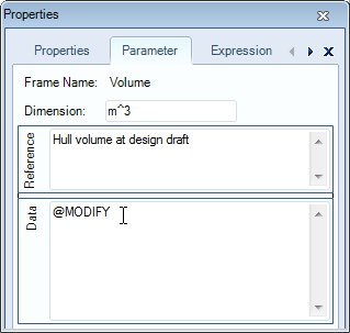
In the Domain Expert version of the tutorial, it was shown that a user can modify calculated values after they are determined by the system, if this is configured so the the Knowledge Engineer. You can enable this functionality by adding a @MODIFY attribute to the data slot of the parameter.
- Click on the parameter
Volumein the Knowledge Browser, select the Parameter tab of the Properties window and enter@MODIFYin the Data field.
3 Modify parameter display order
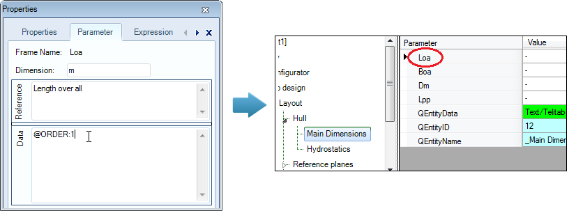
It can be desirable to influence the parameter display order in the Workbase list. Normally, Quaestor puts parameters in alphabetal order. An @ORDER attribute on a parameter defines the relative position of the parameter in the Workbase list. Define this position by: @ORDER:RelativePosition, in which RelativePosition is an integer. The @ORDER values need not be consecutive. Parameters are sorted on RelativePosition from low to high. Values with no @ORDER attribute are placed below parameters with @ORDER attributes.
Here, as an example, you will place parameter Loa at the top of the list. It is up to you to order the other parameters.
- Click on the parameter
Loain the Knowledge Browser, select the Parameter tab of the Properties window and enter@ORDER:1in the Data field.
4 Define minimum and maximum values for parameters
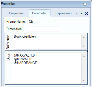
Another interesting feature to assist the user, is to provide feedback about minimum and maximum input values. Moreover, you can make these boundaries into hard ranges in order to prevent the user from providing values that might cause faulty results.
As an example, you can define a minimum and a maximum for the parameter Cb. This value must lie between 0 – 1.0. The system should issue a warning if the computed or input value is not within this range. This is done by means of the attributes @MAXVAL and @MINVAL. If you want the system to force a value inside this range, add @HARDRANGE as well.
- Add the following attributes to parameter
Cb:@MAXVAL:1.0,@MINVAL:0,@HARDRANGE
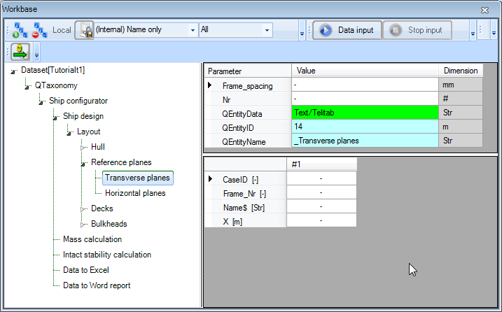
5 Have a parameter determine the number of cases in an entity
Parameter Nr will be used to indicate the number of cases (columns) in an entity.
Provide parameter Nr with the special attribute @NRINST (Data field of Parameter tab in Properties window). The @NRINST attribute tells Quaestor that the value given/calculated for this parameter indicates the number of instances/cases in an object (in this case an Entity). TODO ??? (ASR)
It is useful to also provide Nr with the attribute @INTEGER. The @INTEGER attribute limits input or computed values of the parameter to integer values. If a non-integer value is either computed or provided, the system issues a warning and prompts for other input or for new input of other parameter values that lead to this result. In addition, for this integer value you should change the number of decimal places to 0.
6 Make parameters multicase
Normally, the value of any single value parameter is displayed in the list view.
The @MULTVAL attribute forces a single value parameter to present itself in table form. The @MULTVAL attribute is used in parameters if you wish to obtain a table which includes all values of these parameters whether they are single values or not. See also the Domain Expert tutorial.
The following parameters need to be shown in the table: Name$, CaseID, Frame_Nr and X. So you have to set a @MULTVAL attribute on these. By doing this, you can see thethese parameters being moved from list view to table view (you might have to refresh Quaestor with Ctrl+U to redraw the Workbase).
7 Provide default values
- Create the following relation for parameter
Xin entityTransverse planesin the Workbase:
X = Frame_nr * (Frame_spacing/1000)
For each case, representing a transverse reference plane, this relation will be calculated. Parameter Frame_spacing does not have a @MULTVAL attribute, thus the value provided for Frame_spacing will be constant for each case.
It is possible to provide a default value for a parameter, that can be overruled by the user.
- Enter 700 in the Value cell of
Frame_spacing.
8 Use of ORCA() to generate case numbers
- Create the following relation for parameter
CaseIDin entityTransverse planesin the Workbase:
CaseID = ORCA(1)
The function ORCA(1) returns the current case number (during execution). Later on this calculated value is used to refer to one of the transverse reference planes.
Incidentally, you could also have made this relation in the Knowledge Browser and connected it to entity's parameter.
9 Parameters to show extra information
Every entity is automatically created with three parameters, QEntityData, QEntityID and QEntityName. These are hidden from the output by default. The first one can show behing-the-scenes computed values. In addition, parameters QEntityDoc and QEntityRef can also show extra information.
- Include
QEntityDocandQEntityRefin theHydrostaticsandTransverse planesentities by drag/drop from the Knowledge Browser. - Set the attribute @SHOW on
QEntityData,QEntityIDandQEntityName.
You can add a picture in QEntityDoc, which explains definitions of reference planes and the coordinate system of the vessel to the user in the Explanation window.
- Right-click on
QEntityDocin entityTransverse planesand select Taxonomy>Include Binary Data or press Ctrl+B. Select the file thet you want to include (e.g. the provided picturereference_planes.bmp).
Comparable to assigning a reference to a parameter, you can assign a reference to an entity. As the value QEntityRef you can enter an unlimited entity reference text, which will be shown in the html Explanation window. For example; “Define number of transverse reference planes”
10 Make a parameter type local to an entity
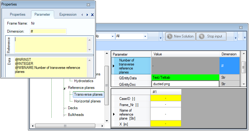
You can use the @WBNAME parameter attribute to define a display name that differs from the name of the parameter itself. For example, you want to define a display name Number of transverse reference planes for parameter Nr. Because you want this name to be unique for entity Transverse planes you cannot simply add the attribute to the data slot of the parameter!
Right-click
- on parameter
Nr
- in entity
Transverse planes
- and select
Taxonomy>Instantiate “Nr”
- (or press
Ctrl+E
- ).
Now, the background of the Propertieswindow for this parameter the textfield turns to yellow. This means that you are now able to set properties and provide a reference text and attributes for the parameter which differ from the global reference text and attributes for this parameter.
You can restore the parameter to the global settings by again pressing Ctrl+E or selecting Taxonomy>Set global ”Nr” from the context menu.
After making parameter Nr in entity Transverse planes local in this way:
- Set the attribute
@WBNAME:Number of transverse reference planes - Change the reference text to
Number of transverse reference planes. - Do the same for parameter
Name$(make it local,@WBNAME:Name of reference plane, reference:Name of transverse reference plane)
Remember that you can define a display sequence of the parameters in a specific entity by setting @ORDER attributes for localized parameters.
Finally the entity Transverse planes should look like this:
2.3.7 Entity “Horizontal planes”
The explanation for this paragraph will be extensive than the previous, because most of the actions that have to be performed are equal to the actions described above.
The main goal is that we want to create the possibility for the user to define a table with a number of horizontal reference planes. For each plane the user has to define a position and a name.
Provide parameter “Z” also with an attribute @MULTVAL in the Data Slot of the parameter.
- Next include the following parameters in Entity “Horizontal planes“: “Nr”, “Name$”, “CaseID”, “Z”, “QEntityData”, “QEntityDoc”and “QEntityRef”.
- Parameters “Nr”, “Name$” and “Z” will be requested to the user (so all are VR parameters). Instantiate the parameters “Nr” and “Name$” in Entity “Horizontal planes” and provide for both parameters a @WBNAME attribute to define a presentation name for the user.
- Create the following relation CaseID = ORCA(1)
- To show computed values during a dialogue write “@SHOW” behind “QEntityData”.
- Add picture “reference_planes.bmp” as Binary to “QEntityDoc”.
- Assign the following text for “QEntityRef”; “Define number of horizontal reference planes”
Now your developed Entity “Horizontal planes” should more or less look like Figure 75.

Figure 75: Entity "Horizontal planes"
2.3.8 Entity “Decks”
Entity “Decks” will be developed as a container which contains combined data of all defined singular decks below. As child of Entity “Decks” we include the multiple (select one of more) Entity “Deck”.
| Deck | child of “Decks” | Entity type: Multiple (select one of more) |

As depicted in Figure 21 below Entity “Decks” can contain one or more “Deck” Entities, each containing the same parameters and relations; however the user can provide different input values for every Deck.
During the dialogue the user will be asked the number of Deck Entities he wants to include. If you include the “Nr” parameter in the “container” Entity “Decks” this will be the parameter which determines the number of “Deck” Entities that will be placed, because “Nr” contains an @NRINST attribute in the Data Slot, as explained in 2.3.6.1.
- Create the following parameters in the Knowledge Browser.
Parameter name | Dimension | Reference |
Total_deck_area | [m^2] | Total deck area |
Deck_data# | [Telitab] | Table of deck data |
Total_accommodation_area | [m^2] | Total accommodation deck area |
Total_accommodation_area# | [Telitab] | Table of all accommodation deck data |
Please note “#” behind a parameter name automatically indicates this will be a Telitab in Quaestor, which mean this parameter can contain Text, a List or a Table. We now will use it to create a Table. For more detailed information about a TeLiTab see TeLiTab.
- Next include the following parameters in Entity “Decks“: “Nr”, “Total_deck_area”, “Deck_data#”, “Total_accommodation_area”, “Total_accommodation_area#”, “QEntityRef” and “QEntityData”.
We will include relations for these parameters at a later stage (in paragraph 2.3.10), because these will be clearer to you when you first have developed Entity “Deck”.
2.3.9 Entity “Deck”
- Create the following parameters in the Knowledge Browser.
Parameter name | Dimension | Reference |
B | [m] | Width |
Area | [m^2] | Area |
Deck_function$ | [$] | Define function of deck |
L | [m] | Length |
Weight_area_factor | [t/m^2] | Weight factor per area |
X_aft | [m] | Aft deck position in X (longitudinal) direction |
X_front | [m] | Front deck position in X (longitudinal) direction |
X_aft_plane_ID | [ID] | Define aft (longitudinal) position of deck by selecting a transverse reference plane |
X_front_plane_ID | [ID] | Define front (longitudinal) position of deck by selecting a transverse reference plane |
Z_plane_ID | [ID] | Define Z (vertical) position of deck by selecting a horizontal reference plane |
- Next include the following parameters in Entity “Deck“: “Name$”, “Area”, “B”, “Deck_function$”, “L”, “Weight_area_factor”, “X_aft”, “X_aft_plane_ID”, “X_front”, “X_front_plane_ID”, “Z”, “Z_plane_ID and “QEntityData”.
Provide the following relations (the explanation of the relations will follow):
- B = ENTITY#(xx).Boa (for xx fill in the value of QEntityId of Entity “MainDimensions”
- Area = L*B
- L = X_front - X_aft
- To show computed values during a dialogue write “@SHOW” behind “QEntityData”.
Please note all parameters in Entity “Deck” should be in the list View and not in the table view, because all values are constant single values. So, parameters “Z" and “Name$” “in Entity “Deck” are automatically placed in the table view because you have provided a @MULTVAL attribute to these parameters earlier. You can instantiate the parameters in Entity “Deck” and remove the @MULTVAL attribute locally.
A second option is to provide @NOMULTVAL attribute in parameter “QEntityData” of Entity “Deck”. Now all @MULTVAL attributes within this Entity will be ignored.
The user (ship designer) has to indicate the starting position and end position of a deck in longitudinal direction of the ship, with the parameters “X_aft” and “X_front”. This determines the length “L” of the ship. Next we assume the width “B” of a deck is equal to the width over all “Boa” of Entity “MainDimensions”. To assume rectangular decks the area is calculated by L*B.
You might wonder why we have added the “Weight_factor_area” parameter. Although we will come to this in section 2.4.1.2 of this part, the main reason is that this parameter is a property of the Deck and as such should part of the “Deck” Entity. However, hereafter we will discover that we do not want to give the input for this value in this Entity, but as part of the “Mass calculation” Entity. In order not to show the parameter in this Entity do the following:
- Instantiate the parameter;
- Add the @HIDE attribute to hide is.
How to connect the start and end position to the reference planes will be discussed next.
2.3.9.1 Create selection list of reference planes with @SELECTENTITY attribute to position deck
We want to create a selection list from available data to position a deck according to specified reference planes in the reference Entities.
The way to do this will be explained by determining the aft position of a deck.
Include the following attributes in the Data Slot of parameter “X_aft_plane_ID”, see Figure 76:
- @SELECTENTITY; the value or string Entity attribute @SELECTENTITY:QEntityID is used to create a selection list from data available in other Entities. You have to replace QEntityID with the value of QEntityID you want to refer to, in this case Entity ““Transverse planes”.
- @SELECTENTITYKEY; the value or string parameter attribute @SELECTENTITYKEY:PAR is used to define the key parameter for the selection in a table of the Entity selection list (created by @SELECTENTITY). You have to replace PAR with the parameter you want to select. In this case we want to select the value of parameter “CaseID”.
- @SELECTENTITYKEYTEXTPAR; the value or string parameter attribute @SELECTENTITYKEYTEXTPAR:PAR is used to define the parameter for selection in the Entity in the Entity selection list, a pointer to a sub Entity. In this case we want to select the value of parameter “Name$”
- @EQEXPLAIN; the value or string parameter attribute @EQEXPLAIN is used to show the description instead of the values (for instance in a combo box).

Figure 76: Create selection list of transverse reference planes with @SELECTENTITY attribute
Please note that the value “14” of Entity “Transverse planes” as presented in this tutorial can differ from your knowledge base, because it depends on the sequence of creating Entities in a Taxonomy Entity tree!
By including the attributes as described above, the user can select a reference plane from a drop down list, containing the names of all defined transverse reference planes. The result of the selection is a value of parameter “CaseID”, but the value of parameter “Name$” is presented to the user.
The value of parameter “X_aft” should be the value of “X” from the selected transverse plane. This can be done by the following relation:
- X_aft = ENTITY#(14).X.X_aft_plane_ID
This means the following: Entity “Transverse planes” (in this example Entity#(14)) contains a table of transverse planes, in which each column (case) represents a transverse plane. When the user has selected the second name from the table, the value of “X_aft_ID” = 2 (although “Name$” is presented to the user). So the value of “X_aft” equals to the second “X” value from the table within Entity “Transverse planes”:
- X_aft = ENTITY#(14).X.2
Next, include exactly the same attributes for parameter “X_front_ID” as you did for “X_aft_ID” and provide the following relation.
- X_front = ENTITY#(14).X.X_front_plane_ID
And finally do the same for “Z_plane_ID”. Please note now you have to refer to the QEntityID of Entity “Horizontal planes, in our example “15”. Create the following relation:
- Z = ENTITY#(15).Z.Z_plane_ID
2.3.9.2 Provide @OBJECTTITLE to a multiple Entity like Deck
As shown in Figure 21, each Entity node name of a Deck contains the name and height of a deck. This can be developed by using the attribute @OBJECTTITLE in parameter “QEntityData” of Entity “Deck”. Behind this value you can provide a flexible string, for example.
- @OBJECTTITLE:"Deck_" + Name$ + "; deck height = " + STR$(Z) + " m"
In here everything place between quotes will be presented as text. The value of a string parameter like “Name$” will also be shown as text. Finally if you also want to present a value of parameter (which is not a string by itself) within the node name of an Entity you first have to make a string of it, for example STR$(Z). See help function of Quaestor or STR$().
To add the @OBJECTTITLE attribute to QEntityData, double click on the parameter value. The content will open in a larger Quaestor text editor.
2.3.9.3 End result Entity “Deck”
The end result of Entity “Deck” is presented in Figure 77.

Figure 77: Entity "Deck"
Please note that you can always change the presentation sequence of parameters by using a @ORDER attribute, see section 2.3.2.4 of this part. You can include presentation names for parameters which differ from the parameter name itself as explained in section 2.3.6.7. In Figure 77 this is done for parameter “Name$”.
2.3.10 Create relations in Entity “Decks” which combines data from child Entities below
We want to create a table with a subset of parameter values of all defined decks. The QEntity() expression collects parameters of all child entities.
Create the following relation in Entity “Decks”:
- Deck_data# = QEntity(@Name$, @Deck_function$, @Z, @X_aft, @X_front, @Area)
We want to present the total accommodation area separately. Therefore, parameter “Total_accommodation_area#” is introduced that should be a table (Telitab) that only contains data of decks with a "Deck_function$" = "Accommodation". We use the QUERY# function, which returns a Telitab subset on the basis of a set of search criteria
- Total_accommodation_area# = QUERY#(Deck_data#, "NullString", “Accommodation":"Deck_function$")
Next sums of the datasets are made using the SUM function. Create the following relations:
- Total_deck_area = SUM(Deck_data#, 1, "Area")
- Total_accommodation_area = INCASE(Total_accommodation_area# = "0" + Qcrlf, THEN, 0, ELSE, SUM(Total_accommodation_area#, 1, "Area"))
You see that the second relation has a condition (the INCASE() function). If “Total_accommodation_area#” is an empty table (which is possible if the user do not create decks with "Deck_function$" = "Accommodation") then the total accommodation deck area is 0 [m2]. Because the content of an empty table in Quaestor will be: "0" + Qcrlf (in which Qcrlf is a Carriage return-line feed string constant) this should be the value to test the parameter on.
Please note see in the rest of the wiki for more detailed information about functions used above.
- Add the “QEntityRef” and “QEntityData” parameters to “Decks”;
- Assign the following text for “QEntityRef”; “Combined data of all decks” as explanation to the user.
- To show computed values during a dialogue write “@SHOW” behind “QEntityData”.
2.3.11 Entity “Bulkheads”
As mentioned in the first part, this ship configurator uses a different Entity structure for defining (transverse) bulkheads in comparison with defining decks. Of course the same Entity structure could be used, but it is more instructive to present (and develop) a different approach.
The development of the Bulkhead Entity is comparable to the Decks Entity. However, in the previous paragraphs we used a multiple Entity to enable the user to define one or more decks. Now we will develop an Entity where the user can create one table to define one or more transverse bulkheads instead of several Deck entities. Create another child Entity “Bulkheads” below the existing Entity “Bulkheads”.
| Bulkheads | child of “Bulkheads” | Entity type: singular obligatory |

- Create the following parameters in the Knowledge Browser.
Parameter name | Dimension | Reference |
H | [m] | Height |
X_plane_ID | [ID] | Define X position of bulkhead by selecting a transverse reference plane |
Z_bottom | [m] | Bottom position bulkhead in Z (vertical) direction |
Z_top | [m] | Top position bulkhead in Z (vertical) direction |
Z_bottom_plane_ID | [ID] | Define bottom Z (vertical) position of bulkhead by selecting a horizontal reference plane |
Z_top_plane_ID | [ID] | Define top Z (vertical) position of bulkhead by selecting a horizontal reference plane |
- Next include the following parameters in last created Entity “Bulkheads“: “Nr”, “Name$”, “Area”, “B”, “H”, “Weight_area_factor”, “X”, “X_plane_ID”, “Z_bottom”, “Z_bottom_plane_ID”, “Z_top”, “Z_top_plane_ID and “QEntityData”.
Take care that with exception of parameter “Nr” and “QEntityData” all parameters are placed within the table view (if not, instantiate the relevant parameters and provide attribute @MULTVAL in Data Slot).
- To show computed values during a dialogue write “@SHOW” behind “QEntityData”
Again we want to create a selection list from data in the reference Entities to position in this case a bulkhead. In section 2.3.9.1 of this part we explained how to achieve this.
Use this method for the new parameters: “X_plane_ID”, “Z_bottom_plane_ID”, and “Z_top_plane_ID”.
Next create the following relations:
- Area = B*H
- B = ENTITY#(xx).Boa (for xx fill in the value of QEntityId of Entity “MainDimensions”, or navigate with your arrow keys
- H = Z_top - Z_bottom
- X = ENTITY#(xx).X.X_plane_ID (for xx fill in the value of QEntityId of Entity “Transverse planes”)
- Z_bottom = ENTITY#(xx).Z.Z_bottom_plane_ID (for xx fill in the value of QEntityId of Entity “Horizontal planes”)
- ENTITY#(xx).Z.Z_bottom_plane_ID (for xx fill in the value of QEntityId of Entity “Horizontal planes”)
- Z_top = ENTITY#(xx).Z.Z_top_plane_ID (for xx fill in the value of QEntityId of Entity “Horizontal planes”)
As for the parameter in Deck, the parameter “Weight_factor_area” show be instantiated and be provided with the @HIDE attribute. We will come back to this parameter in section 2.4.1.3 of this part.
The end result of Entity “Bulkheads” is presented in Figure 78.

Figure 78: Entity "Bulkheads"
Overview
Content Tools