1 Start process manager
In what follows, you will configure a very simplified virtual ship design and perform all optional analyses that are included in the knowledge base. This should give you a good impression of the process flow and will discuss the most common aspects of performing a Quaestor analysis based on the taxonomy approach.
A new design configuration starts with opening the Process Manager.
- Click on the Process Manager Button. Click Yes when asked if you want to create a new solution and give it a meaningful name.
After you have provided a solution title and continue, a tree structure is built in the Workbase in which the first node (entity) has the name of your solution. This has a child Ship configurator and this has a child Ship design.
2 Select process steps
An options window appears which shows the available process steps. You can select those that you want to perform:
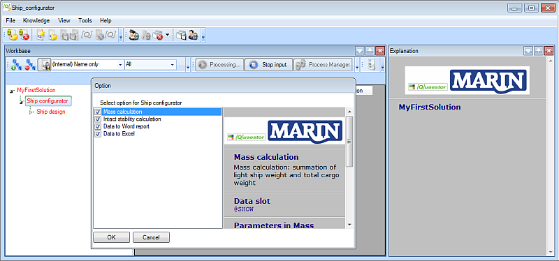
- For this tutorial, select all of them and click OK.
Please note that you can also decide to carry out only a part of the process steps. When you want to add other steps later, select the entity Ship configurator, press Ctrl+F5 and the options window will reappear.
Quaestor automatically checks dependencies between process steps. For example, select “Intact stability calculation” only. Now Quaestor automatically selects “Mass calculation” because “Intact stability calculation” apparently requires information from “Mass calculation”.
3 Select optional entities
After selecting the process steps, some entities are added to the tree structure. Now, you can select the optional entities Decks and Bulkheads.
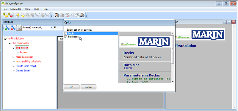
- For this tutorial, select both of them and click OK.
When you have selected the options Decks and Bulkheads, both entities are added below entity Lay out.
Entities can have one of three colors:
- red : user input is required within the entity or child entities below, to determine all information needed for this entity
- blue : no more user input is required within this entity; nevertheless some information is not yet determined. A reason can be that information in other entities has to be determined first.
- black : all information within the entity is determined, thus no user input is required and or no parameters need to be calculated.
4 Navigate processes
As soon as you start a new solution, the process buttons change their status and names. When you click the active button Next, the next input is asked. Stop input does just that. There can be other actions mentioned as well. There is now also a Calculate All button. When you click it, Quaestor will try to calculate all blue entities within your solution.
To perform an analysis, carry out changes, etc. the Quaestor process has to be started by clicking Data input. The process is active when the Next button is shown and stopped when the Data input button is shown again.
In general, working through the process is very straightforward. You can provide input values that are presented in the Workbase either in white or light blue and click Next. You are guided in a “logical sequence” through the whole conceptual design process (for this Ship configurator) as developed by the knowledge engineer (the developer of the knowledge base).
You can always decide to carry out only part of the conceptual design steps or provide the input in a different order. Just go to the pertaining parts in the tree and continue. Any relation between necessary input and steps in the process is taken care of by Quaestor. In other words, when input is required, it will eventually be requested. Furthermore, it is shown by the colors of the entities.
5 Provide input values
Now, entity Main Dimensions is in focus and input values are requested in the list view:
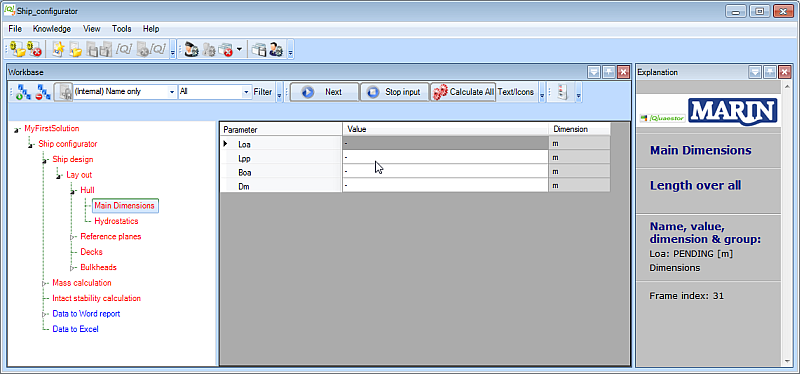
A white cell means that input values from the user are needed.
While scrolling through the parameters in the list view, the Explanation window shows the descriptions and explanations for the selected parameter.
Once an input value is given, the cell color changed to light blue. You can always change your input values later on.
- Enter input values as shown here and click Next:
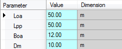
Now, entity Hydrostatics becomes selected in the tree:
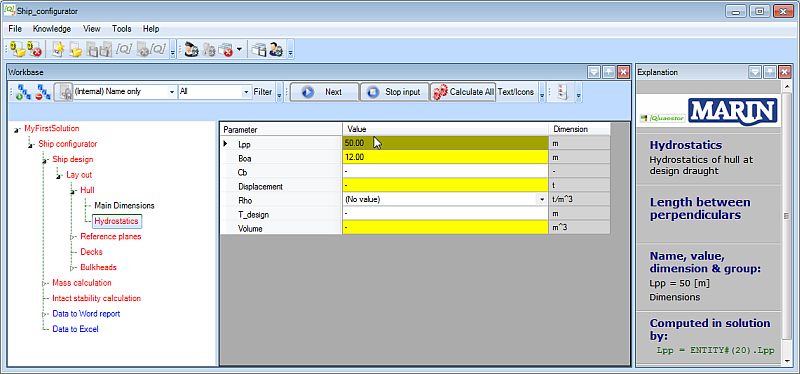
You see that yellow and white cells are shown. A yellow cell means that a value is a Top Goal for the analysis (inside the entity) and it will be determined by a relation. For example, select Lpp in the Entity (shown in Figure 13) and you can see that the value is computed by means of the relation Lpp = Entiy#(20).Lpp, as shown in the Explanation window on the left.
If you do not have the explanation part “Computed in solution by:”, please select Tools > Options > Explanation and check Requested by/determined by.
A Knowledge Engineer can define a minimum and/or maximum value for a parameter. Quaestor will issue a warning if the computed or input value exceeds the indicated boundaries.
- Enter value
2for parameterCband press Enter.
A warning message appears, telling you that Cb should be between 0 and 1. After you click OK, you will see that the value does get accepted anyway!
- Enter input values as shown here and click Next:
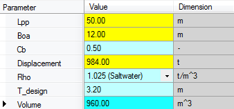
Please note that the resulting value for parameter Volume is presented as a light blue cell, which is the default color to present an input value. However, this parameter is calculated by Volume = Cb*Lpp*Boa*T_design, as you can see when you select the parameter and look in the Explanation window. The reason is, that parameter Volume is defined as a special proposed value, which can be edited after calculation. When you modify the proposed value, the cell will turn red in order to indicate that a proposed value is modified. To return to the proposed value again, select the value and press the space bar to delete the value and press enter. Now the proposed value is calculated and shown again in light blue.
6 Define the reference planes
For the ship configurator, it is decided to define reference planes first. These can then be used to locate other objects like Decks and Bulkheads in a ship design, and then define the arrangement itself. Whenever you change a value of a single reference plane, Quaestor propagates the changed value through the whole solution. Therefore, using reference planes is a powerful method to develop a parametric design.
Now, entity Transverse planes will be selected in the tree. The definitions of reference planes and the coordinate system of the vessel are shown in the Explanation window with a schematic picture. The picture size can be changed by resizing the Explanation window. The default proposed value of parameter “Frame_spacing” is 700 [mm], which can be modified. You have to provide the number of transverse reference planes you want to add to your solution
- Enter 2 as the number of transverse reference planes and press Enter. Select New empty Case(s) from the window that pops up after this.
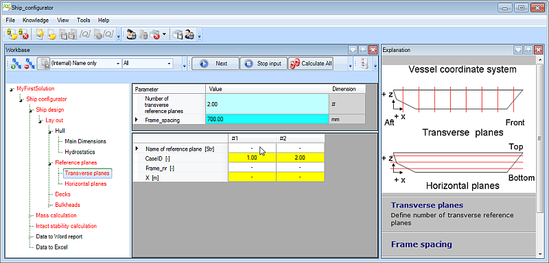
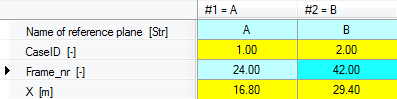
Now a table of 2 columns is created in the table view, each representing a transverse reference plane. You have to enter a frame number and a name for every plane (any recognizable name will do). Quaestor will calculate the X position of a transverse reference plane by X = Frame_nr * Frame_spacing.
- Enter input values as shown here and click Next:
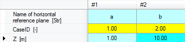
The horizontal reference planes will be defined by the same procedure.
- Select entity
Horizontal planesin the tree. - Enter 2 as the number of horizontal reference planes and press Enter. Select New empty Case(s) from the window that pops up after this.
- Enter input values as shown here and click Next:
7 Define decks and bulkheads
You have selected optional entity Decks, so you have to indicate the number of Deck entities you want to include and these automatically be placed below entity Decks. In this tutorial we need two decks.
- Select entity
Decksin the tree. - Enter 2 as value of the
Number of decksand press Enter.
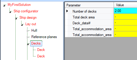
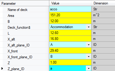
Next you have to define a name and a deck function for every deck. A deck function can be selected from a drop down box. To locate a deck within your ship design, you have to relate the aft and front position of a deck to one of your defined transverse reverences planes and the height of a deck to one of your defined horizontal reference planes. You can refer to your defined reference planes by selecting one of your defined reference names that will be shown in a drop down menu.
As you can see above, the total accommodation area will be computed at the level of entity Decks. Total_accommodation_area results from the summation of all areas of Deck's, using the Deck_function$ named 'Accommodation'.
- Enter input values as shown here and click Next:
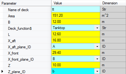
For the second deck the same parameters are requested. Here, another Deck_function$ is used. Please note that in the mean time, the entity node name in the tree view of the first deck is changed into a more recognizable name than just Deck. Now the entity node name of the first Deck contains the name of the deck and the deck height.
- Enter input values as shown here and click Next:
Now, Bulkheads is selected in the tree.
This ship configurator uses ant entity structure for defining (transverse) bulkheads that differs from the one used for the decks. Of course, the same entity structure could be used, but it is more instructive to present a different presentation form. First, you have to provide the number of bulkheads you want to include in your ship design.
- Enter 2 as the value for
Number of bulkheadsand press Enter. Select New empty Case(s) from the window that pops up after this.
Now a table of two columns is created in the table view, each representing a singular bulkhead. After completing entity Bulkheads the ship lay out is completed.
- Enter input values as shown here and click Next:
4.10 Mass calculation
If the ship lay out is finalized (it is always possible to change values afterwards) the first analysis, Mass calculation, can be performed. Figure 23 presents Entities below Entity “Mass calculation”. In here the mass and the centre of gravity of the whole system will be calculated, which depends on the mass and centre of gravity of both light ship weight and weight of cargo objects. The total mass is calculated by the summation of all mass components. The centre of gravity of a system of components is defined as the average of their positions, weighted by their masses. This method is used at every level within the Mass calculation.

Figure 23: Tree view mass calculation
At the level of Entities “Mass Calculation”, “Light ship Weight” and “Mass Cargoes” no input is requested to the user. So click “Accept input & Continue”. Quaestor calculates all information in these Entities when all required information from lower Entities is available.
4.11 Provide input values for Entity Mass Hull
Based on the results of Entities “Main Dimensions” and “Hydrostatics” below Entity “Hull” the centre of gravity and volume of the hull is determined. Scroll through the parameter list to see the used relations in the Explanation window. For this simplified ship configurator we assume that the mass of the hull can be computed by:
Mass = Weight_volume_factor* Volume
As user you only have to provide a weight volume factor, for example 0.5 [t/m3], see Figure 24. The moments around the X, Y and Z axis are determined by Mass multiplied by respectively COGX, COGY and COGZ.

Figure 24: Example input Entity "Mass hull"
4.12 Mass calculation of Decks and Bulkheads
In section 4.8 you already defined the names and positions for a number of decks; in this tutorial two decks were defined. Entity “Decks”, below Entity “Mass Decks”, presents a table, containing for each defined Deck; the deck name, the (deck) area and the centre of gravity, see Figure 25.

Figure 25: Provide weight factor for every deck you have defined
Again, a yellow cell means that a value is a top Goal for the analysis and it will be determined by relations. The parameters “Nr”, “Name of deck”, and “Area”, are automatically copied from the defined “Deck” Entities below Entity “Lay out”. When you add or remove a deck, or change properties of an existing defined deck, these adaptations will automatically propagated to the “Mass Decks” Entity.
The centre of gravity of a deck is based on the given location in your ship design. For this simplified ship configurator we assume that the mass of the decks can be computed by:
Mass = Weight_area_factor* Area
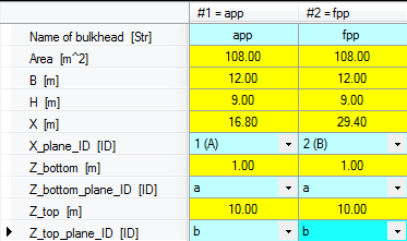
As user you only have to provide a weight area factor for each deck, for example 0.02 [t/m2] and 0.03 [t/m2]. The mass calculation as applied for decks is also used for the mass calculation of bulkheads. Figure 26 shows example input for Entity “Bulkheads” below Entity “Mass Bulkheads”.

Figure 26: Example input values Entity "Bulkhead" below Entity "Mass Bulkheads"
4.13 Define number of cargo objects
Besides the light ship weight calculation it is possible to define the name, COG and mass of a number of cargo objects. Further explanation is not needed. Example input values are given in Figure 27. Please note a schematic picture in the Explanation window depicts the vessel coordinate system as support for the user.

Figure 27: Example input values Entity "Cargoes"
4.14 Intact stability calculation
The mass and centre of gravity of the whole system are input for the intact stability calculation. For this tutorial a very unrealistic simplified stability|Co calculation is developed. The moment of area inertia of the waterline area is the only required input value.
Entity “Intact stability” is only included to give an idea how a configurator can be build with a taxonomy approach. Example input values for Entity “Intact stability” is presented in Figure 28.

Figure 28: Intact stability calculation
4.15 Data to Word report
At the moment you leave Entity “Intact stability” with the "Accept input & Continue" button Quaestor jumps automatically in Entity“Data to Word report”. In here you do not have to provide any input values. Quaestor will directly generate (if all information from the previous Entities is available) a little MS Word report. When you have this document open at that moment, you will see the generation of the reports on your screen.
Please be aware that fatal errors may occur when you are actively working in Word while the reports are generated. Therefore, please wait until the documents are closed.
There are two ways to open the created Word documented from inside Quaestor.
- Select the parameter Report_document$ in Entity “Example report” and click on “Click here for value” in the Explanation window below “Name, value & dimension”.
- Double click on the report name behind the parameter Report_document$ (in Figure 29 “Report_151212_2.doc”).
Finally, it is always possible to find and open the document in your project folder on your computer. The example report document is built up from two sub documents (two chapters) that also can be watched / opened separately.

Figure 29: Generation of example MS Word report
4.16 Data to Excel
The main dimensions and a table of deck data will also be written to an Excel file. In here the total deck area will be calculated and the result will be send back to Quaestor in parameter “Total_deck_area”, see Figure 30. If Quaestor knows all the required data the Excel file will be made at the moment you are in Entity “Data to Excel”.
Please note that the knowledge engineer (the developer) can decide whether to leave the Excel sheet (or Work document) open or close it automatically. In the case of the Excel sheet it has been chosen to leave the Excel sheet open.
There are two ways to open an Excel file from Quaestor.
- Select the parameter File_name_Excel$ in Entity “Data to Excel” and click on “Click here for value” in the Explanation window below “Name, value & dimension”.
- Double click on the Excel file name behind the parameter File_name_Excel$ (in Figure 30 “Deck_data_153402.xls”).
Finally it is always possible to find and open the document in your project folder on your computer.

Figure 30: Data to Excel
Back to content | Back to Explanation user interface | For knowledge engineers: Continue with the tutorial on the creation of a Taxonomy type knowledge base >>
Overview
Content Tools