Global Coordinate System (GCS)
The snapshot below displays the position and attitude of the optimist with respect to the Global Coordinate System (GCS) in the Offshore Basin. The xy-plane of the GCS is aligned with the Still Water Line (SWL). The x-axis points towards the 180deg wave maker in the basin. This wave maker located opposite to the control room. The z-axis points upwards and intersects position K8 on the basin floor. Multiple steady wind velocity measurements were conducted in January 2023 at three elevations (0.50m, 1.00m and 1.50m). Xy-positions of the wind probe array were inside the inner yellow contour. These measurements were converted into a spatial non-temporal wind field for the simulation model. Outside the yellow inner contour the wind velocities are by default set to zero in the simulation model. The outer contour represents the boundaries of the basin floor. Practically, it is also not possible to sail in the area between both contours in the Offshore Basin due to the presence of objects (carriage, wind bed) and the recirculation of the generated flow.
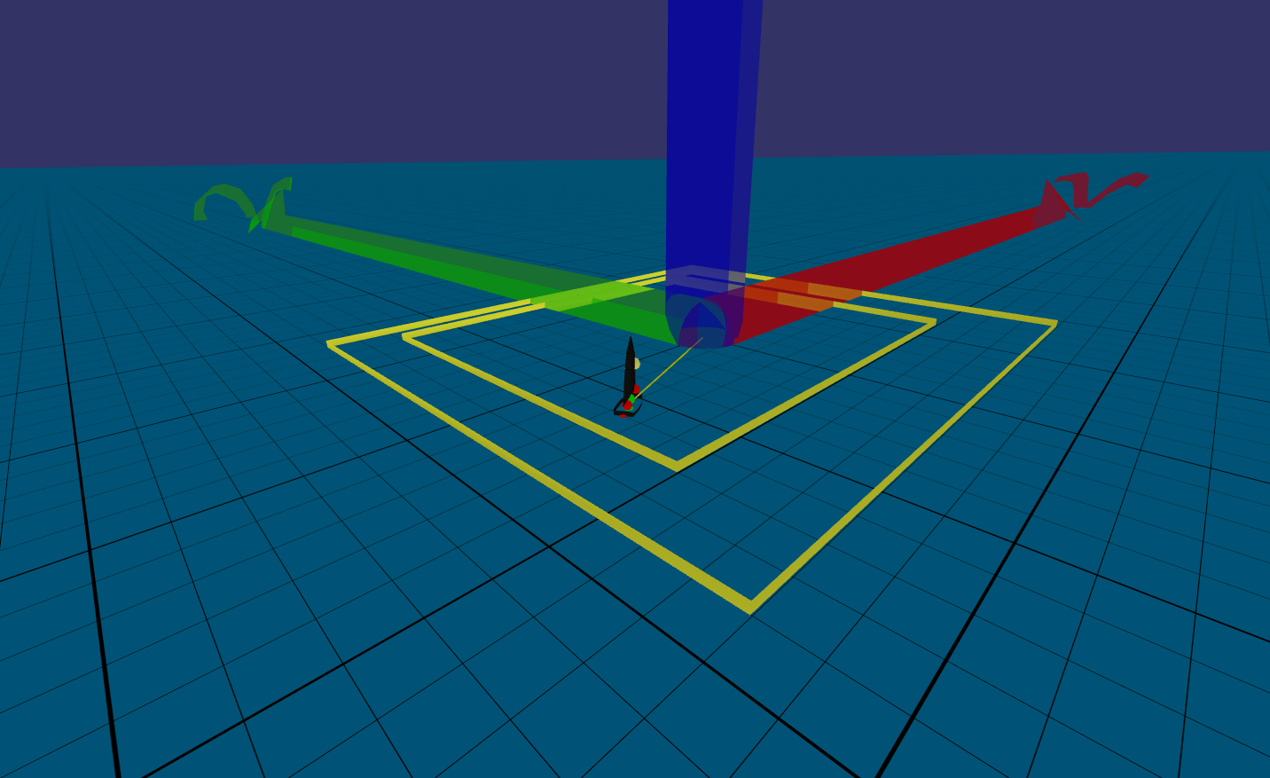
Figure: Snapshot of the Optimist in the Offshore Basin
Boundaries of the inner contour:
- Longitudinal range (27m): -14m<x<13m
- Lateral range (24m): -10m<y<14m
In the figure below measured longitudinal velocities at z=1.00m are presented. Each line represents a constant x-coordinate for multiple measurements of different y-coordinates. You can observe, that the velocity drops significantly towards the edges in lateral direction. Good sailing conditions are mainly in the range of -5m to 5m in lateral direction. Deviations in longitudinal direction are present, but less pronounced.
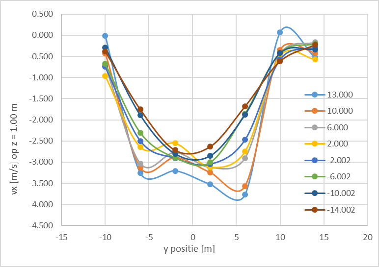
Figure: X-component wind velocity vector at 1.00m (40% setting)
The Optimist Body Conventions
The Optimist assembly consists of three bodies denoted as hull, boom and ballast. These bodies are linked together by means of constraints. The largest and heaviest body is the hull which accommodates all actuators. The boom is connected to the hull by means of a hinge joint. The ballast can shift in lateral direction by means of a prismatic joint between the hull and the ballast body. The right-handed Local Coordinate Systems (LCS) of the three bodies are displayed in the figure below. If the boom (and the sail) has a boom angle of 0 degrees w.r.t. the hull, the orientation of these three LCS's is equal. The origin of the boom is at the intersection between the boom profile and the centerline of the mast. The origin of the ballast is chosen at the center of the aluminum profile, which is the support of the ballast actuator on the hull edges. The board and rudder are objects. They have a frame of reference, but have not inertia like a body.
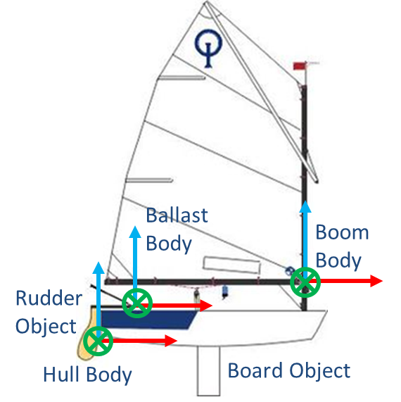
Figure: Sketch of the body origins and attitudes (x=red, y=green, z=blue)
In the table below the relative positions of the ballast body and boom body are listed.
Table: Offset Ballast Body LCS and Boom Body LCS w.r.t. Hull Body LCS
| Body | x[m] | y[m] | z[m] |
|---|---|---|---|
| Ballast | 0.576 | 0.000 | 0.505 |
| Boom | 2.041 | 0.000 | 0.674 |
The as-built mass and inertia properties are listed. The position of the CoG is specified with respect to the origin of the associated body.
Table: As-built body mass/Inertia properties w.r.t. LCS
| Body | mass[kg] | x[m] | y[m] | z[m] | kxx[m] | kyy[m] | kzz[m] |
|---|---|---|---|---|---|---|---|
| Hull | 108.959 | 1.041 | 0.000 | 0.238 | 0.414 | 0.744 | 0.729 |
| Ballast | 42.591 | 0.000 | 0.000 | 0.000 | 0.113 | 0.153 | 0.176 |
| Boom | 1.651 | -0.970 | 0.000 | 0.340 | 1.183 | 1.438 | 1.014 |
The values from the above table can be converted to the properties for a single lumped body. Those values are displayed below.
Table: As-built body mass/Inertia properties lumped bodies w.r.t. LCS Hull
| Lumped Body | mass[kg] | x[m] | y[m] | z[m] | kxx[m] | kyy[m] | kzz[m] |
|---|---|---|---|---|---|---|---|
| Hull-Ballast-Boom | 153.201 | 0.912 | 0.000 | 0.321 | 0.381 | 0.650 | 0.637 |
Other relevant main particulars are listed in the table below.
Table: As-built main particulars of the Optimist assembly
The time trace from a numerical roll decay is displayed below.
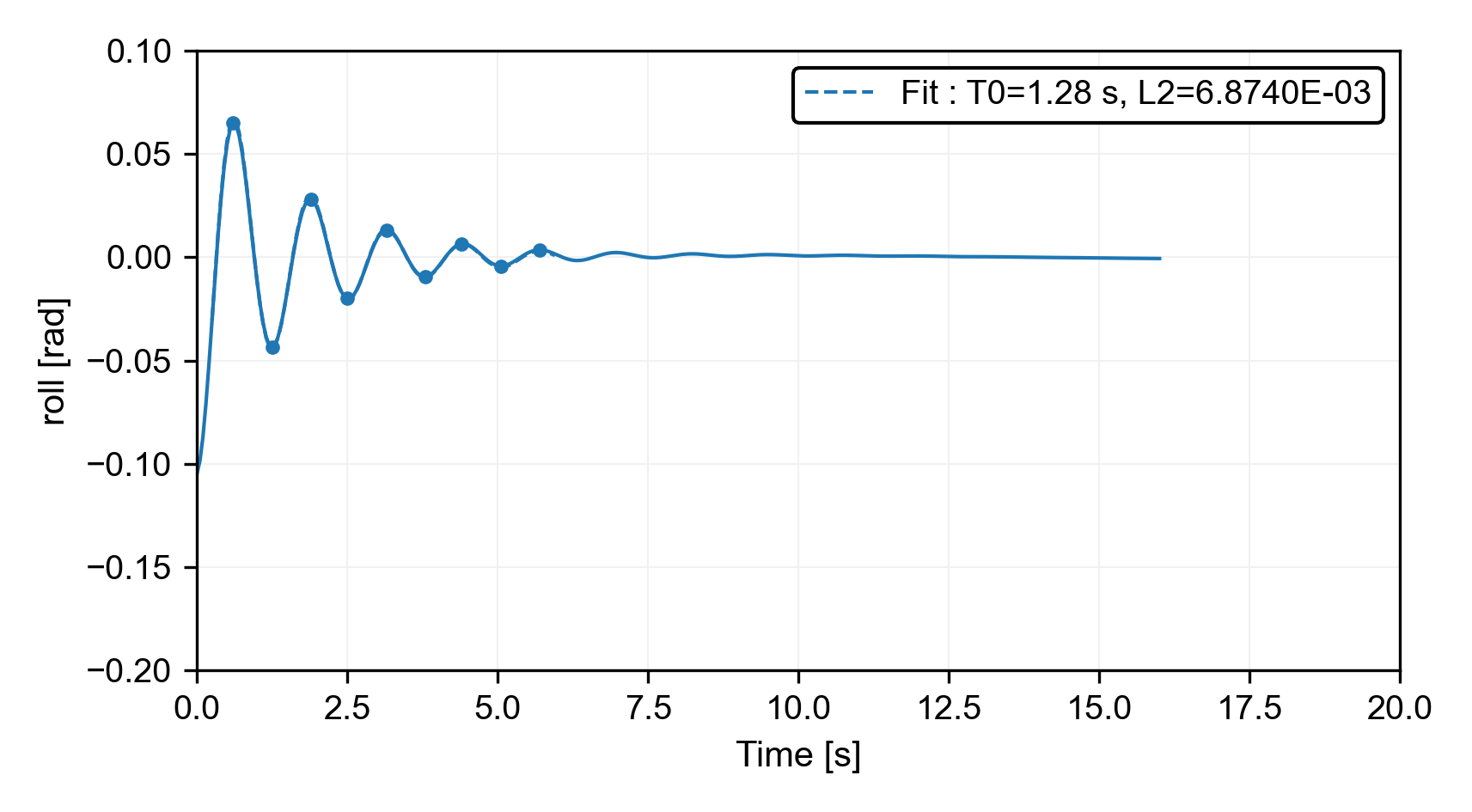
Figure: Roll decay from simulation, T=1.28s, highly damped mode
Overview
Content Tools