In this section you will develop the ship design process further.
- Include the following entities:
| child of | Singular obligatory |
| child of | Singular obligatory |
| child of | Singular obligatory |
| child of | Belongs to group of single optional Entities |
| child of | Belongs to group of single optional Entities |
How to include entities is described in the previous sections.Th result so far should look like this:
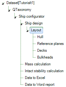
A ship design always contains a layout with at least a hull and defined reference planes. The entities Decks and Bulkheads will be optional for a user to include in their ship design.
Entity Hull
- Include the following two entities as children of
Hull:
| Singular obligatory |
| Singular obligatory |
Entity Reference planes
- Include the following two entities as children of
Reference planes:
| Singular obligatory |
| Singular obligatory |
Entity “Decks”
Entity “Decks” will be developed as a container which contains combined data of all defined singular decks below. As child of Entity “Decks” we include the multiple (select one of more) Entity “Deck”.
| Deck | child of “Decks” | Entity type: Multiple (select one of more) |

As depicted in Figure 21 below Entity “Decks” can contain one or more “Deck” Entities, each containing the same parameters and relations; however the user can provide different input values for every Deck.
During the dialogue the user will be asked the number of Deck Entities he wants to include. If you include the “Nr” parameter in the “container” Entity “Decks” this will be the parameter which determines the number of “Deck” Entities that will be placed, because “Nr” contains an @NRINST attribute in the Data Slot, as explained in 2.3.6.1.
- Create the following parameters in the Knowledge Browser.
Parameter name | Dimension | Reference |
Total_deck_area | [m^2] | Total deck area |
Deck_data# | [Telitab] | Table of deck data |
Total_accommodation_area | [m^2] | Total accommodation deck area |
Total_accommodation_area# | [Telitab] | Table of all accommodation deck data |
Please note “#” behind a parameter name automatically indicates this will be a Telitab in Quaestor, which mean this parameter can contain Text, a List or a Table. We now will use it to create a Table. For more detailed information about a TeLiTab see TeLiTab.
- Next include the following parameters in Entity “Decks“: “Nr”, “Total_deck_area”, “Deck_data#”, “Total_accommodation_area”, “Total_accommodation_area#”, “QEntityRef” and “QEntityData”.
We will include relations for these parameters at a later stage (in paragraph 2.3.10), because these will be clearer to you when you first have developed Entity “Deck”.
2.3.9 Entity “Deck”
- Create the following parameters in the Knowledge Browser.
Parameter name | Dimension | Reference |
B | [m] | Width |
Area | [m^2] | Area |
Deck_function$ | [$] | Define function of deck |
L | [m] | Length |
Weight_area_factor | [t/m^2] | Weight factor per area |
X_aft | [m] | Aft deck position in X (longitudinal) direction |
X_front | [m] | Front deck position in X (longitudinal) direction |
X_aft_plane_ID | [ID] | Define aft (longitudinal) position of deck by selecting a transverse reference plane |
X_front_plane_ID | [ID] | Define front (longitudinal) position of deck by selecting a transverse reference plane |
Z_plane_ID | [ID] | Define Z (vertical) position of deck by selecting a horizontal reference plane |
- Next include the following parameters in Entity “Deck“: “Name$”, “Area”, “B”, “Deck_function$”, “L”, “Weight_area_factor”, “X_aft”, “X_aft_plane_ID”, “X_front”, “X_front_plane_ID”, “Z”, “Z_plane_ID and “QEntityData”.
Provide the following relations (the explanation of the relations will follow):
- B = ENTITY#(xx).Boa (for xx fill in the value of QEntityId of Entity “MainDimensions”
- Area = L*B
- L = X_front - X_aft
- To show computed values during a dialogue write “@SHOW” behind “QEntityData”.
Please note all parameters in Entity “Deck” should be in the list View and not in the table view, because all values are constant single values. So, parameters “Z" and “Name$” “in Entity “Deck” are automatically placed in the table view because you have provided a @MULTVAL attribute to these parameters earlier. You can instantiate the parameters in Entity “Deck” and remove the @MULTVAL attribute locally.
A second option is to provide @NOMULTVAL attribute in parameter “QEntityData” of Entity “Deck”. Now all @MULTVAL attributes within this Entity will be ignored.
The user (ship designer) has to indicate the starting position and end position of a deck in longitudinal direction of the ship, with the parameters “X_aft” and “X_front”. This determines the length “L” of the ship. Next we assume the width “B” of a deck is equal to the width over all “Boa” of Entity “MainDimensions”. To assume rectangular decks the area is calculated by L*B.
You might wonder why we have added the “Weight_factor_area” parameter. Although we will come to this in section 2.4.1.2 of this part, the main reason is that this parameter is a property of the Deck and as such should part of the “Deck” Entity. However, hereafter we will discover that we do not want to give the input for this value in this Entity, but as part of the “Mass calculation” Entity. In order not to show the parameter in this Entity do the following:
- Instantiate the parameter;
- Add the @HIDE attribute to hide is.
How to connect the start and end position to the reference planes will be discussed next.
2.3.9.1 Create selection list of reference planes with @SELECTENTITY attribute to position deck
We want to create a selection list from available data to position a deck according to specified reference planes in the reference Entities.
The way to do this will be explained by determining the aft position of a deck.
Include the following attributes in the Data Slot of parameter “X_aft_plane_ID”, see Figure 76:
- @SELECTENTITY; the value or string Entity attribute @SELECTENTITY:QEntityID is used to create a selection list from data available in other Entities. You have to replace QEntityID with the value of QEntityID you want to refer to, in this case Entity ““Transverse planes”.
- @SELECTENTITYKEY; the value or string parameter attribute @SELECTENTITYKEY:PAR is used to define the key parameter for the selection in a table of the Entity selection list (created by @SELECTENTITY). You have to replace PAR with the parameter you want to select. In this case we want to select the value of parameter “CaseID”.
- @SELECTENTITYKEYTEXTPAR; the value or string parameter attribute @SELECTENTITYKEYTEXTPAR:PAR is used to define the parameter for selection in the Entity in the Entity selection list, a pointer to a sub Entity. In this case we want to select the value of parameter “Name$”
- @EQEXPLAIN; the value or string parameter attribute @EQEXPLAIN is used to show the description instead of the values (for instance in a combo box).

Figure 76: Create selection list of transverse reference planes with @SELECTENTITY attribute
Please note that the value “14” of Entity “Transverse planes” as presented in this tutorial can differ from your knowledge base, because it depends on the sequence of creating Entities in a Taxonomy Entity tree!
By including the attributes as described above, the user can select a reference plane from a drop down list, containing the names of all defined transverse reference planes. The result of the selection is a value of parameter “CaseID”, but the value of parameter “Name$” is presented to the user.
The value of parameter “X_aft” should be the value of “X” from the selected transverse plane. This can be done by the following relation:
- X_aft = ENTITY#(14).X.X_aft_plane_ID
This means the following: Entity “Transverse planes” (in this example Entity#(14)) contains a table of transverse planes, in which each column (case) represents a transverse plane. When the user has selected the second name from the table, the value of “X_aft_ID” = 2 (although “Name$” is presented to the user). So the value of “X_aft” equals to the second “X” value from the table within Entity “Transverse planes”:
- X_aft = ENTITY#(14).X.2
Next, include exactly the same attributes for parameter “X_front_ID” as you did for “X_aft_ID” and provide the following relation.
- X_front = ENTITY#(14).X.X_front_plane_ID
And finally do the same for “Z_plane_ID”. Please note now you have to refer to the QEntityID of Entity “Horizontal planes, in our example “15”. Create the following relation:
- Z = ENTITY#(15).Z.Z_plane_ID
2.3.9.2 Provide @OBJECTTITLE to a multiple Entity like Deck
As shown in Figure 21, each Entity node name of a Deck contains the name and height of a deck. This can be developed by using the attribute @OBJECTTITLE in parameter “QEntityData” of Entity “Deck”. Behind this value you can provide a flexible string, for example.
- @OBJECTTITLE:"Deck_" + Name$ + "; deck height = " + STR$(Z) + " m"
In here everything place between quotes will be presented as text. The value of a string parameter like “Name$” will also be shown as text. Finally if you also want to present a value of parameter (which is not a string by itself) within the node name of an Entity you first have to make a string of it, for example STR$(Z). See help function of Quaestor or STR$().
To add the @OBJECTTITLE attribute to QEntityData, double click on the parameter value. The content will open in a larger Quaestor text editor.
2.3.9.3 End result Entity “Deck”
The end result of Entity “Deck” is presented in Figure 77.

Figure 77: Entity "Deck"
Please note that you can always change the presentation sequence of parameters by using a @ORDER attribute, see section 2.3.2.4 of this part. You can include presentation names for parameters which differ from the parameter name itself as explained in section 2.3.6.7. In Figure 77 this is done for parameter “Name$”.
2.3.10 Create relations in Entity “Decks” which combines data from child Entities below
We want to create a table with a subset of parameter values of all defined decks. The QEntity() expression collects parameters of all child entities.
Create the following relation in Entity “Decks”:
- Deck_data# = QEntity(@Name$, @Deck_function$, @Z, @X_aft, @X_front, @Area)
We want to present the total accommodation area separately. Therefore, parameter “Total_accommodation_area#” is introduced that should be a table (Telitab) that only contains data of decks with a "Deck_function$" = "Accommodation". We use the QUERY# function, which returns a Telitab subset on the basis of a set of search criteria
- Total_accommodation_area# = QUERY#(Deck_data#, "NullString", “Accommodation":"Deck_function$")
Next sums of the datasets are made using the SUM function. Create the following relations:
- Total_deck_area = SUM(Deck_data#, 1, "Area")
- Total_accommodation_area = INCASE(Total_accommodation_area# = "0" + Qcrlf, THEN, 0, ELSE, SUM(Total_accommodation_area#, 1, "Area"))
You see that the second relation has a condition (the INCASE() function). If “Total_accommodation_area#” is an empty table (which is possible if the user do not create decks with "Deck_function$" = "Accommodation") then the total accommodation deck area is 0 [m2]. Because the content of an empty table in Quaestor will be: "0" + Qcrlf (in which Qcrlf is a Carriage return-line feed string constant) this should be the value to test the parameter on.
Please note see in the rest of the wiki for more detailed information about functions used above.
- Add the “QEntityRef” and “QEntityData” parameters to “Decks”;
- Assign the following text for “QEntityRef”; “Combined data of all decks” as explanation to the user.
- To show computed values during a dialogue write “@SHOW” behind “QEntityData”.
2.3.11 Entity “Bulkheads”
As mentioned in the first part, this ship configurator uses a different Entity structure for defining (transverse) bulkheads in comparison with defining decks. Of course the same Entity structure could be used, but it is more instructive to present (and develop) a different approach.
The development of the Bulkhead Entity is comparable to the Decks Entity. However, in the previous paragraphs we used a multiple Entity to enable the user to define one or more decks. Now we will develop an Entity where the user can create one table to define one or more transverse bulkheads instead of several Deck entities. Create another child Entity “Bulkheads” below the existing Entity “Bulkheads”.
| Bulkheads | child of “Bulkheads” | Entity type: singular obligatory |

- Create the following parameters in the Knowledge Browser.
Parameter name | Dimension | Reference |
H | [m] | Height |
X_plane_ID | [ID] | Define X position of bulkhead by selecting a transverse reference plane |
Z_bottom | [m] | Bottom position bulkhead in Z (vertical) direction |
Z_top | [m] | Top position bulkhead in Z (vertical) direction |
Z_bottom_plane_ID | [ID] | Define bottom Z (vertical) position of bulkhead by selecting a horizontal reference plane |
Z_top_plane_ID | [ID] | Define top Z (vertical) position of bulkhead by selecting a horizontal reference plane |
- Next include the following parameters in last created Entity “Bulkheads“: “Nr”, “Name$”, “Area”, “B”, “H”, “Weight_area_factor”, “X”, “X_plane_ID”, “Z_bottom”, “Z_bottom_plane_ID”, “Z_top”, “Z_top_plane_ID and “QEntityData”.
Take care that with exception of parameter “Nr” and “QEntityData” all parameters are placed within the table view (if not, instantiate the relevant parameters and provide attribute @MULTVAL in Data Slot).
- To show computed values during a dialogue write “@SHOW” behind “QEntityData”
Again we want to create a selection list from data in the reference Entities to position in this case a bulkhead. In section 2.3.9.1 of this part we explained how to achieve this.
Use this method for the new parameters: “X_plane_ID”, “Z_bottom_plane_ID”, and “Z_top_plane_ID”.
Next create the following relations:
- Area = B*H
- B = ENTITY#(xx).Boa (for xx fill in the value of QEntityId of Entity “MainDimensions”, or navigate with your arrow keys
- H = Z_top - Z_bottom
- X = ENTITY#(xx).X.X_plane_ID (for xx fill in the value of QEntityId of Entity “Transverse planes”)
- Z_bottom = ENTITY#(xx).Z.Z_bottom_plane_ID (for xx fill in the value of QEntityId of Entity “Horizontal planes”)
- ENTITY#(xx).Z.Z_bottom_plane_ID (for xx fill in the value of QEntityId of Entity “Horizontal planes”)
- Z_top = ENTITY#(xx).Z.Z_top_plane_ID (for xx fill in the value of QEntityId of Entity “Horizontal planes”)
As for the parameter in Deck, the parameter “Weight_factor_area” show be instantiated and be provided with the @HIDE attribute. We will come back to this parameter in section 2.4.1.3 of this part.
The end result of Entity “Bulkheads” is presented in Figure 78.

Figure 78: Entity "Bulkheads"
Overview
Content Tools